General
These notes document the firmware for the readout system for UCD Prof. Mani Tripathi’s readout module, based on the Analog Devices LTC2324-16 quad serial ADC. Readout is effected using an AMD (Xilinx) 7000 Series Zynq SoC, as implemented on a TUL Pynq-Z2 development board. This board boots a linux OS into the on-chip processor and then launching a Jupyter Server.
This project is archived at https://github.com/prebys/mani_readout. The current contents are
- Xilinx/mani_readout_test/: Location of Vivado project to build the readout test overlay for the Pynq
- Jupyter Noteboks/mani_test_readout/: Location of the .bit, .hwh, and .ipynb files which should be copied to the Pynq to access the overlay.
Zynq Configuration
The FPGA configuration for the Zynq implements two modules, each of which uses one of the PMOD interfaces. The PMOD pin-outs are shown below:
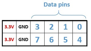
The modules are defined as follows:
- LTC2324_read: This module is designed to interface to the ADC and readout module. External communication is via PMODA, mapped as show below. Definitions of the signals are found in the ADC documentation.
- pin 0 – ext_trigger input. Can be configured to be active HI or active LO. Receiving an external trigger will promptly issued an active LO cnv and initiate a readout cycle. This can also be triggered by a soft trigger, described shortly. Once a readout cycle has been completed, no further triggers are accepted until the data is read out and the module is re-armed.
- pin 1 – cnv output. Active LO signal that is asserted promptly after a trigger and kept asserted throughout the readout process.
- pin 2 – sck output. Serial clock.
- pin 3 – clkout input. Serial return clock. Currently not used in the design.
- pin 4 – sdo input. Serial data from the ADC
Control and readout of the module is done through four GPIO registers, which can be written or read from the Jupyter interface. They are
-
- timing[7:0] (write only) – this controls the time for the convert and the rate of the serial clock. Defined as follows:
- [7:4] – cnv_time: the time the cvt signal should remain low before loading in the first valid data bit, in units of 40ns.
- [3:0] – sck_time: the time for both sck to remain LO and sck to remain HI, in units of 10ns.
- control[7:0] (write only) – this configures and controls the module. The bits are defined as follows:
- [0] – arm: The transition of this bit from LO to HI will put the module in the READY state and enable triggers.
- [1] – soft_trigger: If the module is in a READY state, the transition of this bit from LO to HI promptly issue a cnv output and initiate a readout cycle.
- [6:2] – (not used)
- [7] – ext_parity: Parity of the external trigger. 0-> active HI, 1->active LO. If this is set to one, it should be ORed with the arming bit. Does not affect the parity of the internal soft trigger.
- state[2:0] (read only) – state of the module, with the following values
- READY (0) – module is armed and ready for a trigger, either external or internal.
- CNV (1), SCK_LO (2), and SCK_HI (3) – intermediate states while the conversion and readout are underway.
- DONE (4) – module has completed a readout and valid data is ready. Triggers are blocked until an arm command is received. In normal operation, monitoring for this state is how one knows that a trigger has been received. Module initially comes up in this state and must be armed.
- data[15:0] (read only) – ADC data that has been read back. Valid when state==DONE(4).
- timing[7:0] (write only) – this controls the time for the convert and the rate of the serial clock. Defined as follows:
- LTC2324_dummy: This module is included to test LTC2324_read by generating test data to emulate the ADC. It is externally mapped to PMODB as follows:
- pin 1: dummy_cnv input
- pin 2: dummy_sck input
- pin 3: dummy_clkout output
- pin 4: dummy_sdo output
In other words, if these 4 pins are jumpered to the corresponding pins on PMODA, data will be be read out as specified by the following register
-
- dummy_ADC[15:0] (write only) – data to be read out in test mode.
Accessing the Pynq
This describes the configuration specific to the Pynq board in Physics 373.
The micro-USB port provided power and serial communication to the Pynq board. When the board powers up, it takes a minute two to fully boot up, after which the LEDs will flash several times and then go to steady green. You can communicate with the board using PuTTy, selecting “serial”, the correct COM port, and 15200 baud. On the computer in 373, this had been stored as the “pynq” configuration, using COM5.
You interact with the Jupyter interface over ethernet. This board is set up with a static IP address of 169.254.150.2. To access the server, enter:
http://169.254.150.2:9090/lab
in the browser interface. You may get a warning that no “https” server is available. You may also get a notice to “clear workspace”. If you are asked for a password, it’s “xilinx”. Once you get to the server, you’ll see the Jupyter directory tree. This project is currently in mani_readout/mani_readout_test.
New .bit and .hwh files can be copied to this area by simply dragging them into the file browser window.
Python Communication
Examples of communication and readout are found in the mani_readout_test.ipynb notebook. It expects to find the files mani_readout.bit and mani_readout.hwh in the same directory. Some key parts are as follows
An initial reset overcomes a bug that sometimes happens when uploading new versions of the same configuration file
from pynq import PL
PL.reset()
Then the configuration is then loaded with
from pynq import Overlay
pynq = Overlay("mani_readout.bit")
After that, registers are mapped with
(register name) = pynq.(register name)
Ordinarily, registers must be configured to be inputs or outputs, but since these registers were all created to be unidirectional, you don’t need to worry about that. Write-only registers are written to with:
(register name).write(0,value)
and read from with
value = (register name).read(0)
Examples of arming, triggering and reading out are found in the notebook.
Recent Comments